E21 Lecture #11
Algorithmic State Machine Design
- Separates the design of data processing logic and control logic
- Gives the designer a way to graphically indicate timing and processing actions
Designing the Control Unit
There are three methods you can use to design the control unit.
Design by using a flip-flop for each state
- Convert the ASM control flow to a state machine
- Use one flip-flop for each state in the state machine
- Design directly from the state machine by ANDing the incoming conditions to each state with the state they came from
- When using a register to hold the flip-flop values:
- Invert the logic coming out of the first flip-flop so that when the register is cleared at startup, the first flip-flop has an output value of one
- Invert the logic coming into the first flip-flop so that it represents negative logic
Design with decoders
To simplify output and input variables that rely on the current state, we can use a decoder at the output of the state machine where a single line represents each state.
This is similar to using N flip-flops for N states in that you have N outputs from the state machine, each one corresponding uniquely to a state.
Design with multiplexers
We can design with multiplexers by using them to calculate the next state values
- The output of the current state register is connected to the selector inputs of the MUX
- The output of the MUX is connected to the state register inputs
- The MUX inputs are determined by the input variables and the control flow
- Create a table showing all current state -> next state transitions
- List the different input variable combinations relevant to these transitions
- The corresponding MUX input is the sum of the 1 terms
Example
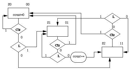
Design a circuit that counts the number of times a laser beam is broken (by someone walking through it, for example). The inputs to the circuit are: Clear, Laser. Clear should reset the counter to 0, Laser indicates whether the beam is broken (1) or not (0). If someone decides to stand in the beam for more than one clock cycle, that should still count as only one "break".