
by Erik Cheever & Bruce Maxwell
For a number of the labs this semester you will be using the computer for data acquisition, data analysis and even experimental control. This is called real-world I/O (Input/Output). Interfacing a computer with the real world is probably new to most of you. In the system in our lab real world interfacing is done with a hardware addition to the computer called a PCI 1200 and a software addition called the NI_DAQ (National Instruments Data AcQuisition) software package. Both are from a company called National Instruments. A full set of documentation for both the hardware and the software is in the lab.
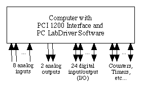
A simple block diagram of the system is shown below. The PCI 1200 can measure up to 8 different analog voltages at speeds up to 62.5 kHz. It has 2 analog outputs that can be used for experimental control. It also has 24 digital connections that can be configured for either input or output. Internally, the board has a set of counters and timers that can be used to control or count events. This document will restrict itself primarily to the analog inputs and outputs. To figure out how to use the other features, consult the appropriate National Instruments documentation.
Analog input to a computer is made possible by the use of an Analog to Digital (A/D or "A to D") converters. These devices take an analog (continuously variable) signal and convert it to a digital number readable by a computer. The 8 analog inputs on the PCI 1200 board have a resolution of 1 part in 4096 (12 bits), and variable gain. If you set the gain to a range of +5 to -5 volts (a low gain) this gives resolution of 1.22 mV. The highest gain returns values in a range from 50 mV to -50 mV, a resolution of 12.2 µV is obtained.
One important characteristic of data acquisition is the sampling frequency--usually measured in samples per second. Acquisition rates may be as high as 62.5 kHz, or 16 µsec per sample.
Using the proper sampling frequency is extremely important, because your sampling frequency has to be at least twice the frequency of the event that you want to capture. This rule is called the Nyquist Criterion. If you fail to follow this rule, then a phenomenon called aliasing occurs. Aliasing is when a frequency higher than half of your sampling frequency gets "folded" back onto a frequency that is less than half your sampling frequency. This creates a ghost signal that can really mess up your results.
Analog outputs are generated through the use of Digital to Analog (D/A or "D to A") converters, which do the opposite of an A/D converter. The 2 analog outputs on the PCI 1200 generate voltages from +5 to -5 volts with a resolution of 1.22 mV. (Note, the actual voltages only reach about +4.99 volts.
There are 24 bits of digital I/O, programmable as either input or output. These signals are TTL (Transistor Transistor Logic, if you don't know what this means, don't worry about it) compatible. TTL compatible means the signals will generally be either close to 0.0V or close to 5.0V.
The PCI 1200 also has six 16 bit timer/counter channels for timing I/O events.
What follows is a brief description of some of the function calls you will need to use to control the PCI 1200 using the NI-DAQ Software. This listing is neither exhaustive nor detailed; to get more information, use the NI-DAQ Manual. An on-line version of the manual is located in the NI-DAQ/Doc folder on the PC. A brief sample program that demonstrates some of these functions is given at the end of this document.
The first thing you must do when using the software is to initialize the PCI 1200 board and NI-DAQ software. This is accomplished with a call to the function Init_DA_Brds() as in the following code snippet..
BoardNumber = 3;
errNum = Init_DA_Brds(BoardNumber, &DevNumCode);
Both variables--BoardNumber and DevNumCode--need to be of type i16, which is equivalent to the type short. Note that you have to pass the address of DevNumCode, as the device number is returned in that variable. The variable errNum needs to be of type short or i16 as well.
The variable BoardNumber should be set to 3 for the current configuration. If the return value assigned to errNum is anything but 0, then an error occurred. Your program should always check for errors, and print out an error message and exit the program if a non-zero value is returned by one of the NIDAQ functions.
Note, since the value of BoardNumber is always 3, it is useful to declare it as a macro rather than a variable--which could potentially be changed. To do this, just use the statement:
#define BoardNumber 3
If you get a non-zero error value, you can determine the error by looking it up in the manual. A code snippet that tests the error value in a useful way looks like the following.
if (errNum != 0) {
  printf("Init_DA_Brds: errNum %d\n", errNum);
  exit(0);
}
The exit(0) function quits your program immediately.
To clear the A/D circuitry--which should be done before starting any analog input operation--use the statement:
errNum = AI_Clear(BoardNumber);
where BoardNumber is a short integer or constant set as above to the value of 3. The prefix AI stands for Analog Input. To read a single analog voltage from the PCI 1200 use the following statement:
errNum=AI_VRead(BoardNumber, channel, gain, &voltage);
BoardNumber is defined as above. The variable channel is a type i16 and specifies the analog input channel from which to grab information. These values are labeled on the front of the input panel underneath the computer monitor. The gain variable is of type i16, and is used to specify the voltage range to be used in the A/D conversion. You can use the table below to pick the correct gain value. Finally, the variable voltage is of type f64 (double), and receives the voltage value on the specified channel. Note that you have to pass in the address of this variable since the routine needs to modify its value.
| gain | resolution | range |
| 1 | 1.22 mV | -5 to 5 V |
| 2 | 0.61 mV | -2.5 to 2.5 V |
| 5 | 0.24 mV | -1 to +1 V |
| 10 | 122 µV | -500 to +500 mV |
| 20 | 61 µV | -250 to +250 mV |
| 50 | 24 µV | -100 to +100 mV |
| 100 | 12.2 µV | -50 to +50 mV |
If you wish, you can also read the digital value of the A/D conversion rather than the voltage value. To do this, use the function AI_Read() rather than AI_VRead().
errNum = AI_Read(BoardNumber, channel, gain, &digitalValue);
The only difference between the arguments of AI_VRead() and AI_Read is that the variable digitalValue needs to be of type i16 since it receives a digital number in the range [0, 4095].
If you wish to convert a digital value to a voltage, you can use the function AI_VScale() as below, where voltage is a .
errNum = AI_VScale(brd, channel, gain, 1.0, 0.0, digitalValue, &voltage);
All of the types are defined as in previous examples, and voltage is a type f64 (double).
To collect multiple consecutive samples you need to do the following operations. First, you need to clear the data acquisition system.
errNum=DAQ_Clear(BOARD);
This function clears any pending data acquisitions. To actually perform a data acquisition operation you first need to determine the timebase and sample interval for the board. These are board specific numbers and, fortunately, there is a function that tells you what they should be for a given sampling frequency.
Once you have selected a sampling frequency, you can determine the timebase and sample interval for the board using the function DAQ_Rate.
errNum = DAQ_Rate(rate, units, &timebase, &sampleInterval);
The variable rate is of type f64 (double) and indicates the sampling frequency in Hertz. The variable units is of type i16 (short) and should be set to 0, indicating that the rate is given in samples per second. The variable timebase should be of type i16 (short), and the variable sampleInterval should be of type u16 (unsigned short). Both timebase and sampleInterval are passed by reference since their values are set by the DAQ_Rate() function.
Once you have set the timebase and sampleInterval variables you can start the data acquisition using the function DAQ_Start().
errNum = DAQ_Start(BoardNumber, channel, gain, valueArray, count, timebase, sampleInterval);
The valueArray variable is an array of type i16. The count variable is of type u32 (unsigned long) and indicates how many samples to take at the rate determined by timebase and sampleInterval. The valueArray array must be large enough to hold count values!
Once the data acquistion has started it is necessary to check for completion because analog I/O operations are often slow compared to the speed of the computer. This is done as follows. The basic idea is that you put the program in a loop until the data acquisition is completed. The following code snippet gives an example of this.
status = 0;
while ((status == 0) && (errNum == 0)) {
  errNum = DAQ_Check(BoardNumber, &status, &retrieved);
}
The variable status is of type i16 (short), and retrieved is of type u32 (unsigned long). If status is 0 then the operation is not yet complete and you must wait. When it is non-zero the operation is done. The value returned in retrieved is the number of data points collected so far.
After the data is collected it is often necessary to convert the short integer values read from the A/D convertor to voltages. Like the AI_VScale() function, you can use the DAQ_VScale() function to make the conversion.
errNum = DAQ_VScale(BoardNumber, channel, gain, 1.0, 0.0, count, valueArray, voltageArray);
where all variables are defined as in previous examples, and the variable voltageArray is an array of type f64 (double) that is large enough to hold count elements.
/****
	This program allows you to interactively capture a series of data from the
	analog inputs of the NIDAQ board. It queries you for the analog channel,
	the total number of samples to take, and the number of samples per second.
	The program then writes out the data to the screen.
****/
/****
	These are include files. They contain data types and
	function prototypes that the compiler needs for your
	program.
****/
#include <stdio.h>		       // standard C I/O library
#include <nidaq.h>		       // Acquisition board library include file

/****
	These are constants that should be easy to set for the
	entire program.
****/
#define MAXDATA 1000			       // Maximum number of data points
#define BOARD 1				       // The slot in which the board resides (should be 1)
#define GAIN 1				       // An integer that determines, in part, the gain on analog
					       // inputs

/****
	The main program starts here
****/
main()
{
  // Variable declarations
  i16             channel,	// which I/O channel to use
                  timebase,	// timing base
                  errNum,	// error detection
                  values[MAXDATA],	// binary values read from the I/O board
                  units = 0,	// pts/s (0) or s/pt (1)
                  devNumCode;	// device number code

  long            count;	// how many samples to take

  u16             sampleInterval;	// sampling interval

  unsigned long   retrieved;	// Boolean value indicating when the sampling is finished

  short           status;	// status variable

  f64             rate,		// samples per second
                  voltages[MAXDATA];	// Final floating point voltages

  FILE           *fp;		// file pointer

  long            i;		// generic loop variable

  char            filename[128];	// filename for output data

  // Get the sampling setup information from the user
  printf("Capture program starting.\n\n");
  printf("Which analog input pin do you want to use? ");
  channel = -1;
  while (channel < 0 || channel > 7) {
    scanf("%hd", &channel);
    if (channel < 0 || channel > 7) {
      printf("The analog input pin must be between 0 and 7\n");
      printf("Please enter a new value: ");
    }
  }
  printf("\nUsing analog input channel: %hd\n\n", channel);

  printf("How many samples do you want to take? ");
  count = -1;
  while (count < 0 || count > MAXDATA) {
    scanf("%d", &count);
    if (channel < 0 || channel > MAXDATA) {
      printf("The number of samples must be between 0 and %d\n", MAXDATA);
      printf("Please enter a new value: ");
    }
  }
  printf("\nCapturing %d samples\n\n", count);

  printf("How many samples per second do you want to take? ");
  rate = -1.0;
  while (rate < 0.0) {
    scanf("%lf", &rate);
    if (rate < 0.0) {
      printf("The rate in samples/sec must be positive\n");
      printf("Please enter a new value: ");
    }
  }
  printf("\nUsing a sampling rate of %lf samples per second\n\n", rate);

  // This routine calculates the internal parameters timebase and sampleinterval
  status = DAQ_Rate(rate, units, &timebase, &sampleInterval);

  printf("(timebase, sampleInterval) = (%hd, %uhd)\n", timebase, sampleInterval);

  // Reset board, clear analog io and check for errors
  errNum = Init_DA_Brds(BOARD, &devNumCode);
  if (errNum != 0) {
    printf("Init_DA_Brds: errNum %d          devNumCode %d\n", errNum, devNumCode);
    exit(0);
  }

  errNum = DAQ_Clear(BOARD);
  if (errNum != 0) {
    printf("DAQ_Clear: errNum %d          devNumCode %d\n", errNum, devNumCode);
    exit(0);
  }

  // Start the data capture
  printf("Starting data capture\n");
  errNum = DAQ_Start(BOARD, channel, GAIN, values, count, timebase, sampleInterval);

  // Wait for acquisition to complete, or an error
  status = 0;
  while ((status == 0) && (errNum == 0)) {
    errNum = DAQ_Check(BOARD, &status, &retrieved);
  }
  printf("Data collection is done, errNum=%d.\n", errNum);

  // Scale the data - ie convert it to voltages.
  errNum = DAQ_VScale(BOARD, channel, GAIN, 1.0, 0.0, count, values, voltages);

  // Write out your results to the screen here
  printf("# Analog Capture: %ld samples taken at %lf samples per second\n", count, rate);
  for (i = 0; i < count; i++)
    printf("%6d %12lf\n", i, voltages[i]);

  return(0);
}